Wavelength Calibration on a Spectronic 20
by kacang bawang
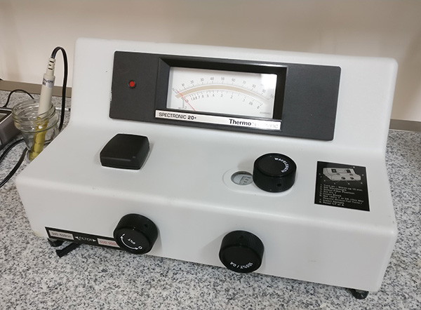
I have recently acquired a used Spectronic 20+. Great instrument in great condition! There was only one problem. It was dropped on its way to me. Read on for a story of restoration and the wavelength alignment procedure.
When it arrived, the box was smashed and I could feel something rolling around inside. Upon opening I found the control knobs have come off from the impact. Little fiber-resin legs shattered into several pieces, bolts bent. Inside, the on/off potentiometer had split apart. Lastly, the bracket that hold the refractive grating in place had split into two.
The potentiometer
Luckily, the potentiometer is rather rugged. It is a simple mechanical device and I was able to put the two halves back together. Watch out for the on/off lock. Bend back the retaining tabs to hold the device together. Test with multimeter.
(Sorry, no pic)
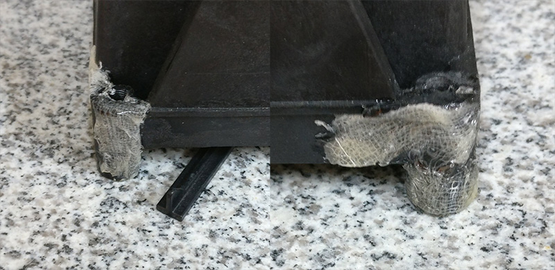
The legs
The legs I glued back together with 2-hour epoxy thoroughly applied between the shattered pieces. Epoxy soaked gauze was added from the outside as additional reinforcement.
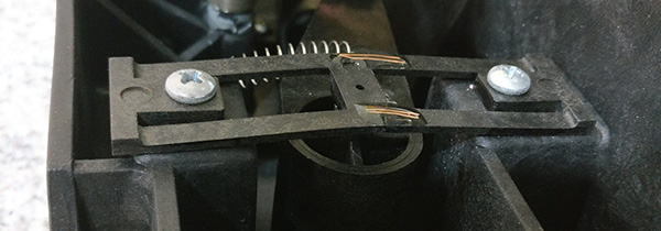
The refractive grating bracket.
The bracket I reattached with epoxy and embedded copper wire, from both sides. The lost pivot ball was replaced by a small ball bearing of matching size.
Is it done yet?
The performance of the spectrometer can be checked with two basic tests, as per the Operating Manual. The first is the wavelength calibration, and second is the photometric linearity.
I conducted the CoCl2 wavelength calibration check only to find that the peak location was shifted +50nm or so. I did not attempt the linearity test in light of this.
But how does one re-calibrate the wavelength? Here is what that same manual states:
If the wavelength accuracy is out of tolerance, refer
to the Service Procedure section on page 3-5.
Customer recalibration is not recommended.
where the “Service Procedure on page 3-5” talks about how to put the instrument into a box and send it to the service center. I wonder how much they would ask for this to be done? Would they even do it in light of the age of the instrument (it is now 2020, born-on-date is 2003)? But as it turns out, the calibration is not that difficult if you have Spectronic Standards set.
So what did I do? That’s right, I found a used standards set in good condition. It may be possible to do this using the cobalt solutions too, it would just be a lot slower as you would have to subtract background at every tested wavelength.
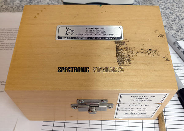
What are the Spectronic Standards (333150)?
It is a nicely packaged set of material slides that are mounted in square cuvettes. There is one standard with transmittance peaks at certain wavelengths, two standards for % absorbance, among others. It is a very useful thing to have for overhauling old Spec 20s. Here is the manual for the standards
NOTE: You will need the square cuvette mounting adapter/holder (333176) to mount the standards in the Spec 20.
I tried 3d-printing a design from scocioba (thank you!) over at shapeways, but the result was not a good fit. As printed, without modification, the walls were too thin and a 10mm cuvette is loose. Keep that in mind if you try to do this.
(3d printed vs original)
Ok, finally, can you now tell me how to calibrate the wavelength?
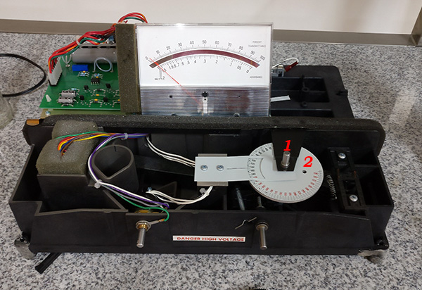
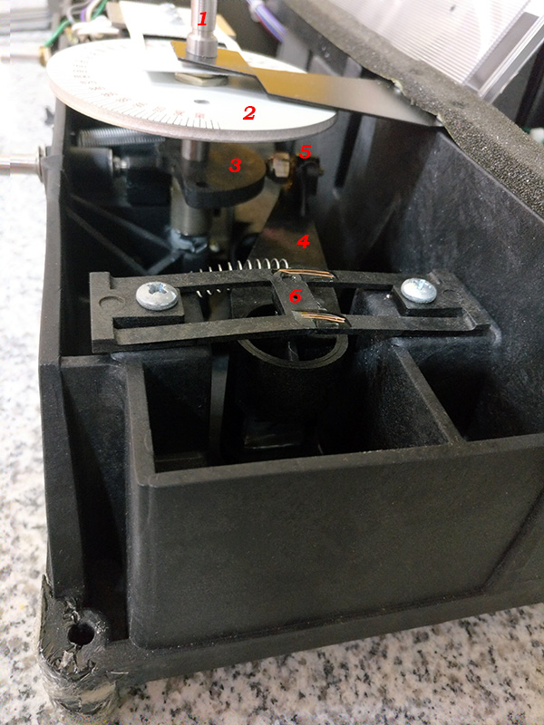
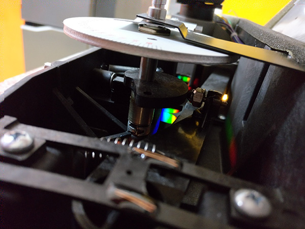
How is the wavelength set on this thing anyways? When you turn the wavelength knob (1), the wavelength dial assembly (2) turns. Mounted on it, there is a bass clef-shaped plastic guide (3) which contacts the diffraction grating arm (4) via a small metal ball point (5). If you have the instrument cover off while running, you can see how the rainbow output of the grating shifts left-right as you rotate the wavelength dial.
The “bass clef” and the wavelength dial are permanently pinned together. The diffraction grating arm, on the other hand, has a fine adjustment by way of screwing the ball-point in and out.
The ball-point threads are sealed with epoxy, which needs to be removed if it is to be rotated again.
The procedure
1. Insert the wavelength standard into the cuvette and dial in to the 525nm wheel position.
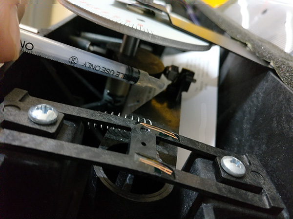
2. Loosen the top diffraction grating arm retaining bracket (6) without removing the bolts completely and slide it around while watching the response of the instrument. Find the position that best lines the transmission peak to the 525nm setting. Keep in mind that it can still be off after this. We are just trying to get as close as we can by only playing with the bracket. Tighten the bracket in place before proceeding to the next step.
3. If Step 2 was enough to align the standard to 525 nm, consider yourself lucky and skip this step. The second place where we can control the wavelength alignment is the little ball-point. Remove the arm bracket, and the arm. Peel the epoxy around the ball-point so that the screw can turn freely.
Removing the epoxy.
My original plan was to soak the epoxy in methylene chloride, TAKING ALL THE CARE IN THE WORLD TO PROTECT THE DIFFRACTION GRATING FROM ACCIDENTAL CHEMICAL OR FINGER CONTACT. However, after applying a few drops of the solvent from a pasteur pipette to the epoxy blob, I noticed a white haze forming on the resin fiber material of which the diffraction grating arm is made of. Not sure if this was the epoxy dissolving and leaving a residue as solvent evaporated or if it was methylene chloride messing with the arm material. So, rather than adding more solvent, I gently tugged on the bolt to see if it would turn. It did. Rather easily, too. Henceforth, I carefully peeled the cracked epoxy pieces with a small screw driver. No further chemical treatment was attempted.
Reassemble the arm bracket, and repeat Step 2. You should now have the instrument on, wavelength standard installed, diffraction grating arm installed, retaining bracket fixed.
Very carefully reach for the ball-point and turn it to make adjustments. After making an adjustment, do a wavelength scan and see where the maximum transmittance lines up. Repeat until you get it to 525nm exactly. If you run out of adjustment, you must go back to playing with the bracket, as these are the only two controls available.
If you don’t have the standards, the wavelength scan can be done in a step-wise manner, taking care to zero at every step using a blank and then measuring transmittance with a CoCl2 solution. Definitely not as easy as just turning the dial.
4. If you have the standards, you can now additionally check wavelength accuracy at 400nm and 780nm.
I got -5nm at 400nm (actual peak at 395nm) and +5nm at 780nm (actual peak at 785nm), after aligning at 525nm.
As you can see, the wavelength accuracy is better closer to 525nm, and poorer away from it. I suppose you could align to 400 or 780nm, instead of 525nm, if all your measurements were going to be in that region. Only the 525nm peak is NIST traceable, however.
5. Apply new epoxy to ball-point if you removed it previously. Prepare some two component epoxy. I recommend letting it sit for about 5 min, or until it starts to get more viscous. Load some into a 1mL syringe and apply a SMALL drop onto the ball-point threads without removing it from the instrument. It helps to put down a business card underneath the work area to protect from accidental drips.
6. Reassemble the instrument and complete the standards test suite.
Here are my results for comparison:
%Tmax: 394, 525, 786 nm
Stray rad: 0.0 %T
SRE: 400nm = 0.0 %T, 340 nm = 5.0 %T, 220nm = N/A
Accuracy: 50%T = 50.6 actual vs 50.6 theory, 10%T = 10.0 actual vs 9.7 theory
7. Beam alignment.
Beam alignment measures where the light hits the sample cuvette. Obviously, it should be centered, and completely within the sample window. How can this be checked? The method given in the Spectronic Standards manual involves cyanotype paper. I actually had some factory-made paper included in the kit, but it seemed to have lost its potency. (Note: the factory paper has a yellow side and a white side, yellow side is the one you want to point towards the enemy light).
I prepared my own cyanotype solution by mixing 1:1 10% potassium ferricyanide and 10% ferric ammonium citrate. Then, I soaked some filter paper in the resultant solution and left it to dry in a dark place. (Note: do not use cardboard as a drying surface, as contact with cardboard turns the cyanotype blue even in the dark. Perhaps it is due to the cardboard being caustic, but I did not investigate further).
Some more hints for exposing the paper. Make sure you have the spectrometer intensity turned up to the max (100%T knob all the way clockwise) and leave it exposing overnight. After exposure, mark the window area before removing the paper from the holder. Unlike written in the Standards manual, you don’t have to expose it to ammonia, just rinse under the sink and dry.
Here is what my result looked like (this is before washing):

A note about Didymium and Holmium standards
There is a more universal way of calibrating wavelengths in spectrometers that is applicable across manufacturers. Didymium and Holmium Oxide cells are used. I happened to receive a pair of these with my standards set (UNICO S-2100-116 and S-2100-115) and so I threw them into the Spec 20+ in an attempt to validate the calibration. To my surprise, the transmission minima (recall, we were looking at transmission maxima for the wavelength standard, don’t get it mixed up) 🙂 did not agree with published high resolution spectra.
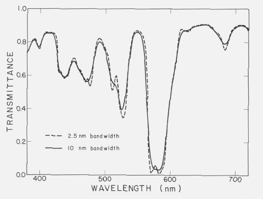
Spectral transmittance of a didymium glass measured on a Zeiss DMC25 spectrophotometer with narrow and wide slits.
Adapted from: Robertson A.R., Standardization in Transmission Spectrophotometry in the Visible and Ultraviolet Spectral Regions, J. Res. Nat. Bur. Stand. (U.S.), 80A (Phys. and Chem.), No.4, 625-630 (July-August 1976).
Spectral transmittance of holmium oxide glass showing 11 NIST certified bands. A line has been inserted for band 8 for clarification. The position of the wavelength minima is the critical parameter, while the level of transmittance can be considered irrelevant. [Spectral bandwidth is 1nm]
Adapted from: D. W. Allen, Holmium Oxide Glass Wavelength Standards, J. Res. Natl. Bur. Stds. 112, No. 6, pp. 303-306 (2007).
My data:
Dy %Tmin: 302, 512, 578, 742, 877 nm
Ho %Tmin: 335, 430 nm
Bandwidth: 20 nm
Why is that? You screwed up the calibration, didn’t you? Not necessarily… The exact peak location is waveband width (and shape) dependent. I could find reference spectra for 1-10nm wavebands for Didymium (here, here) and Holmium (here), but alas the Spec 20 is nominally 20nm, so I still cannot make a conclusive comparison. Anyhow, I present my data above as is, for anyone to compare against other Spec 20’s.