Old School Methods: Transformer-less Power Supplies
by kacang bawang
If you’ve read my previous posts you may be aware that I am in the process of trying to build an electronic device in Indonesia. To this end, I’ve tried to find some local talent to help me. I’ve interviewed a couple of people affiliated with an Indonesian appliance manufacturer who has a factory nearby. Ultimately, none of the candidates were a good fit, but I did learn something new, about which I would like to tell you today.
It turns out that it is possible to transform 110/220 VAC to 5 VDC really, really cheaply and without the use of a transformer. Don’t get too excited though – this method is more of a clever hack and is rather unsafe. It is presented here for educational purposes only.
When I told one of the candidates that I am trying to make an original design of a 220VAC->5VDC module with a low cost, he told me this. Is anyone going to touch it? No, I said, it will be installed into the wall. Then you should just use a capacitor. To be honest, I didn’t believe him. Every power supply that I have ever seen in my life has always used a transformer – there’s no way. But, he was correct… It is possible (not that you should do it that way). The rest of the conversation was uneventful, so with your permission I will skip it.
I arrived at home that evening (this guy’s house was way deep in the kampung) I decided to quickly google this idea – could it really be true? Information was not abundant, but I found some youtube videos showing how it worked. Let me repeat it for you here.
R1 is a current limiting resistor. R2 serves to bleed down C1 when the device is off. C1 is our “transforming” capacitor. D1 eliminates (most of) the negative phase before the current reaches D2. D2 eliminates the rest and thus completes voltage rectification. C2 is a filtering capacitor and D3 is an overvoltage protection zener diode. Choice of C1 influences the current flowing though the DC circuit (as limited by R1) while R3 (the load) influences the voltage in the DC circuit (as limited by D3).
Wait, what? How does that help reduce the voltage? An intuitive way to think about it is to realize that we’re both filling and draining the capacitor at the same time. So as long as our load is connected, and consuming power, the capacitor will never fully charge. Instead, the voltage will settle at some intermediate value. But let me now ask a question that we will answer later – what happens to the voltage in the capacitor if the load is accidentally disconnected?
Sulking from realization of my ignorance, I went to Horowitz looking for answers. The dynamics of a capacitor hooked up to an AC source are described on (p 30) of 2nd edition. We can calculate the current and voltage in our circuit using these formulas:
I = V / (1/(wC)),
where I is current in DC circuit, V is the AC voltage, w is (2Pi * mains frequency) and C is the capacitance of our capacitor
V = IR,
where V is the DC voltage, I is DC current (from above) and R is the resistance of the load
As you can see, the AC source has to be matched with a specific load and a specific capacitance for all this to work. The current limiter and the zener help with small imbalances. I kept reading further and now turned to the section on power supplies (p 328). In Horowitz’s own words:
Never build an instrument to run off the power line without a transformer! To do so is to flirt with disaster. Transformerless power supplies, which are popular in some consumer electronics (radios and televisions, particularly) because they’re cheap, put the circuit at high voltage with respect to external ground (water pipes, etc.). This has no place in instruments intended to interconnect with any other equipment and should always be avoided. And use extreme caution when servicing any such equipment; just connecting your oscilloscope probe to the chassis can be a shocking experience.
Ouch. So much for that idea. And to answer our previous question – what happens to the capacitor voltage if the load is disconnected? That’s right, without something draining it, it will build up to the full mains voltage – 220V. If at this point the load is somehow re-connected, you’re in for a nasty surprise.
Despite Horowitz’s warnings, such transformer-less power supplies can still be found in household goods. In fact, the guy from above, in trying to prove his righteousness said that emergency LED lamps (pic below) use this approach. Well, I just happened to have one of these lamps. In fact, recently it suddenly stopped working and gave off a strong odor of burning plastic, at which point it was promptly unplugged and put in the junk pile.

Now seemed like the perfect time to crack it open and see for myself the transformer-less design. And maybe figure out why it broke. Behold…
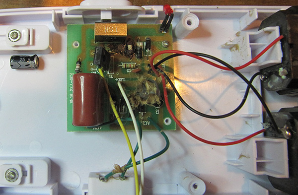
In the picture you can see what ultimately happens to such devices. The thing in the middle is an exploded electrolytic cap, and you can also see some severely overheated resistors. I think one of the positive terminals on the lead cell corroded off and it all went downhill from there.